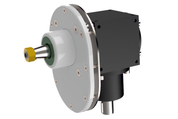
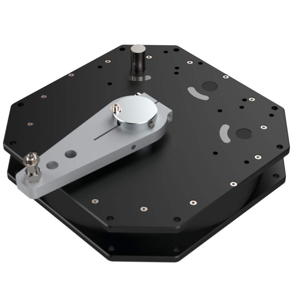
RG10-70 Reduction gearbox (45′ – 65′)
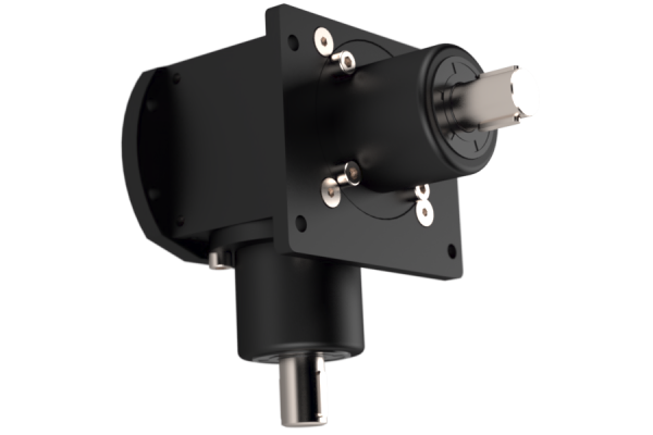
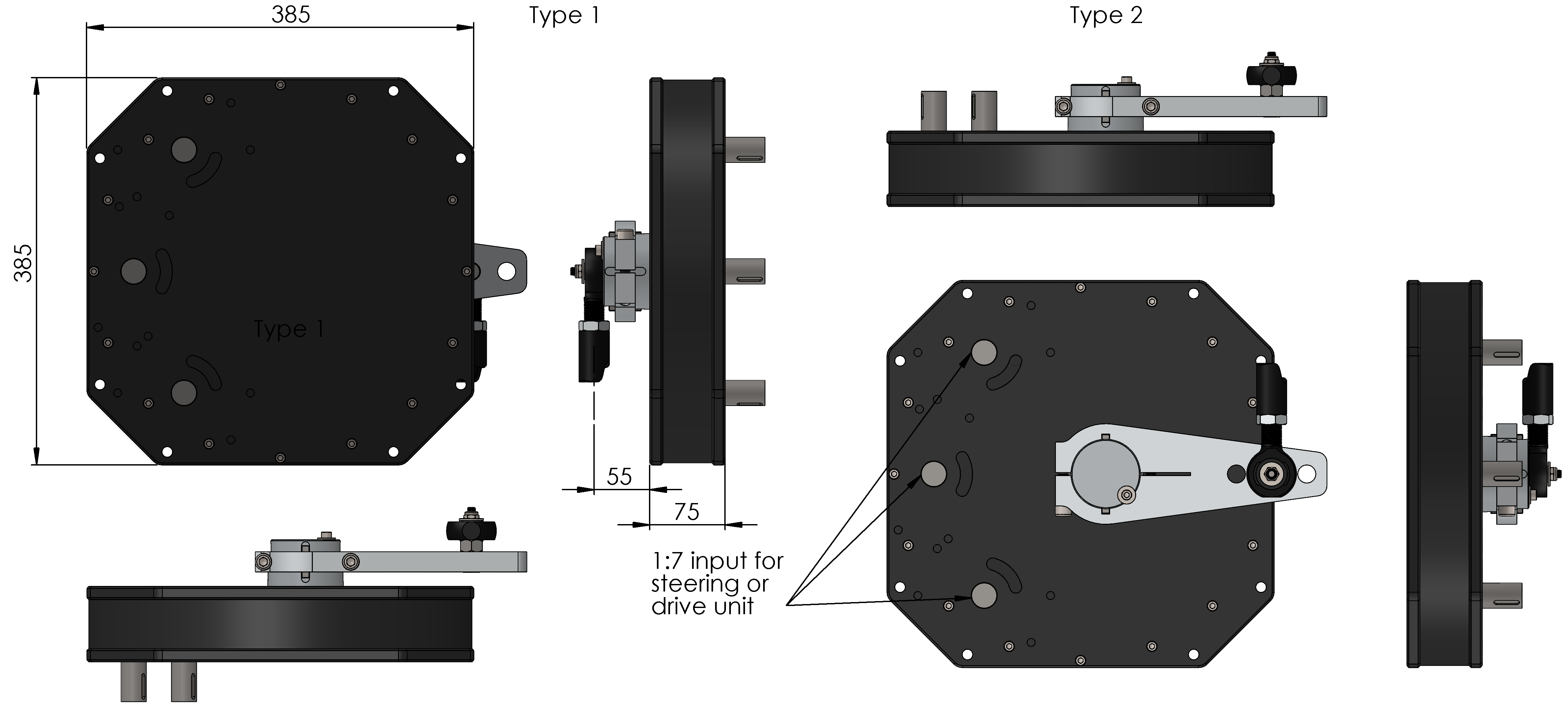
Jefa RG10-70 reduction gearbox transforms a rotational movement into a push-pull movement. The reduction gearbox is always positioned close to the rudder stock. Via a draglink with rose joints, the push-pull movement is transmitted to the tiller lever and rudder shaft. The RG10 gearbox is very versatile as it can be equipped with one (standard), two or three input shafts. On top of that one can choose the output shaft at the opposite side of the input shafts (type 1) or at the same side (type 2). The gear ratio IS 1:7 (2.5 revolutions of the input shaft for a corresponding 72 degrees of rudder travel). The output lever centres are 165 mm to a corresponding 250 mm centres of the tiller lever or 200 mm to a corresponding 307 mm of the tiller lever. This difference in length results in the so called “wide angle geometry”.
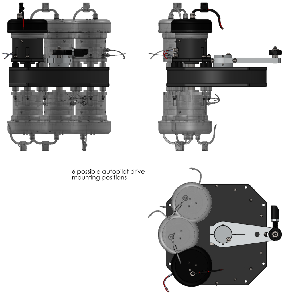
The RG10-70 gearbox has 6 positions to integrate an optional Jefa transmission autopilot drive unit. Integrating an autopilot drive in a steering system has never been so easy.
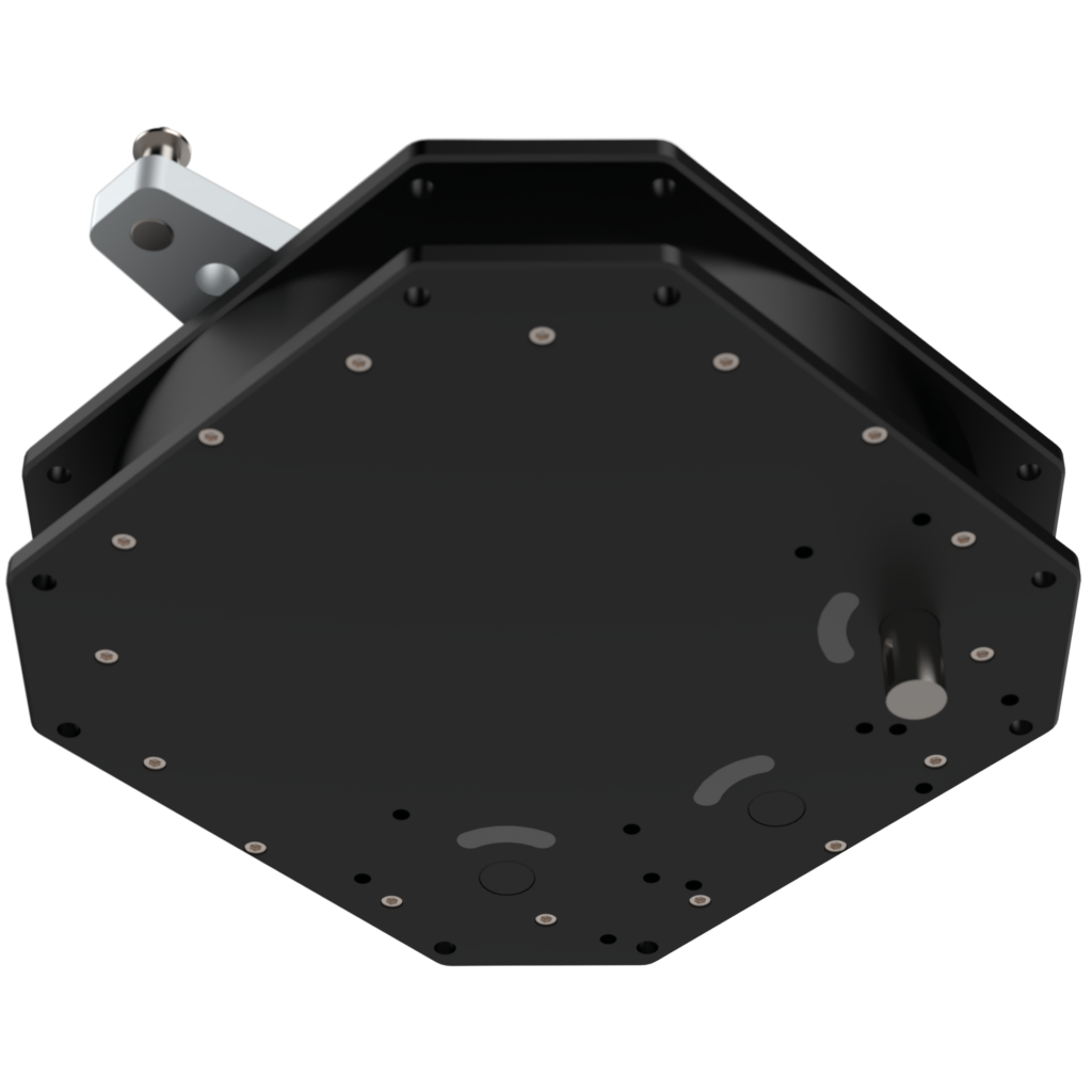
The maximum input torque is 40.5 KgfM resulting in a maximum rudder torque at full rudder of 828 KgfM. The maximum rudder torque according to the CE rating is 291 KgfM midships and 552 KgfM full rudder (the CE regulations use a safety factor of 150%). This makes the gearbox suitable for boats from 45′ to around 65′. Except for the input shafts and the gears, the complete gearbox is machined out of solid aluminium 6082 for maximum strength and minimum weight. Positioning the reduction gearbox correctly to the rudderstock is very important for the wide angle geometry to function correctly. Please look at the mounting examples at the bottom of this page.
Gallery
DATA TABLE
Jefa transmission bevel reduction gearboxes
| Part No. | Description |
|---|---|
| RG10-70 | Reduction gearbox 1:7 including output lever |
| RG10-DB | Shaft and bracket for autopilot for RG10 gearbox |
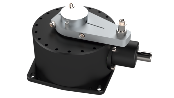
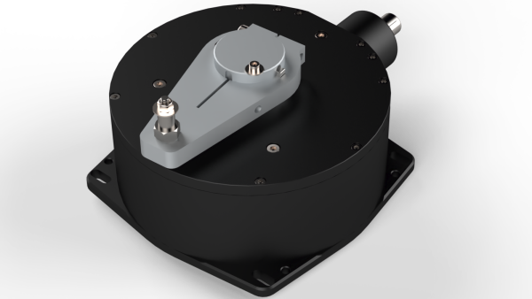
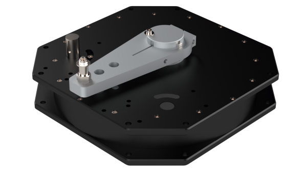
RG10-70 autopilot drive integration
The layout below shows a typical integration of a transmission autopilot drive unit on a type 1 RG10-70 reduction gearbox. The drive can be mounted on 6 positions: 3 at the input side and 3 at the output side.
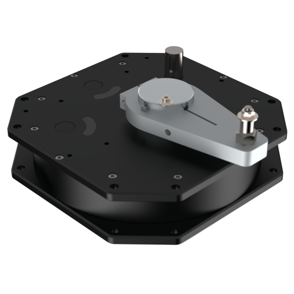
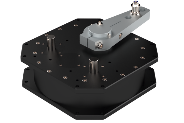
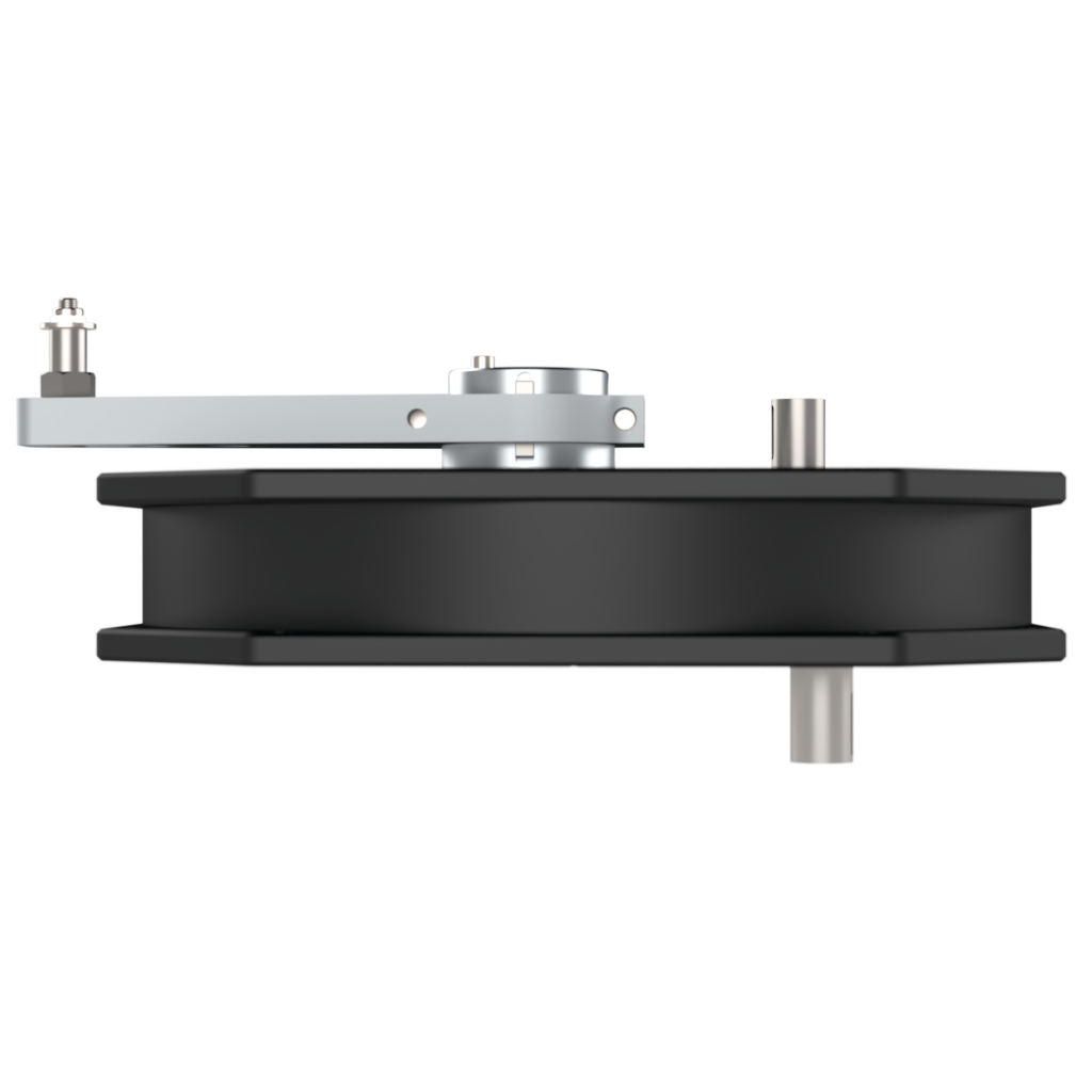
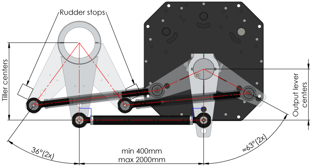
RG10-70 mounting example
The layout below shows a typical installation of a RG10-70 gearbox. The setup is done by having both arms perpendicular to the draglink in midships.
DATA TABLE
RG10-70 operating centres in mm valid for 72° (2×36°) rudder travel.
| Output centre distance | Tiller centre distance |
|---|---|
| 130 (short lever) | N/A |
| 165 (standard long lever) | 250 |
| 200 (extra long lever) | 307 |
Art. 11585